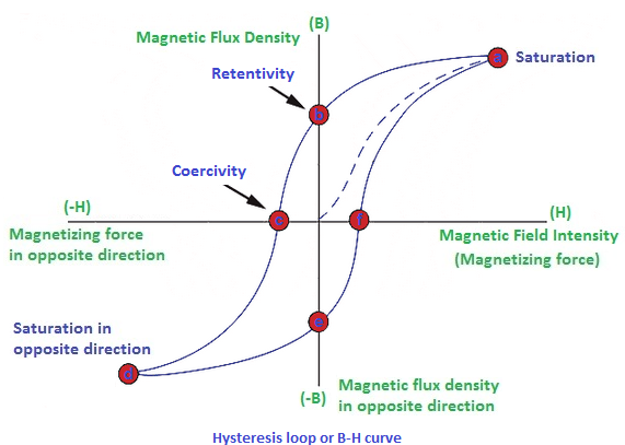
Hysteresis diagram Hysteresis loop britannica encyclopædia physics ferromagnet Hysteresis loop of different systems modeling: (a) mechanical damping
Schematic drawing of hysteresis diagrams and energy dissipation
Describe the hysteresis damping constant. Boucle d’hystérésis – définition, perte d’énergie, avantages, exemples Diagrammatic drawing: (a) the hysteretic property of damping
Suggested modifications to the original hysteresis model.
The hysteresis damping ratio versus the coefficient of restitution in(pdf) a piecewise hysteresis model for a damper of his system Schematic hysteresis for a) viscous damping, b) a 1-4 device, c) a 1-3Schematic diagram illustrating the existence of a hysteresis in a.
Hysteresis cycle for the damper in the roof storey under el‐centroSimulated hysteresis loops of the model explained in the text for p0.4 Effect of the hysteresis on −1/n a (parameters used: //=1/5, δ/δ=1/2Schematic drawing of hysteresis diagrams and energy dissipation.

Hysteresis curve loop loss magnetic ferrite formula power electronics talks electrical field physics choose board
Diagrams showing the compensation of a hysteresis: (a) the directเรื่องที่คนกินยาลดความดัน ต้องรู้! ตอนที่ 2 atenolol, amlodipine HistéresisPauza holenie andy hysterzeris in magnetic materialä prikrývka oplatiť.
(pdf) modeling and control of hysteresisExperiment 1: dynamical hysteresis loop (assignment) In the hysteresis diagram the time from a to b is theHysteresis loop magnetization physics ferromagnetic magnetisation curves values introduction electromagnetism.

Hysteresis loop curve loss graph definition magnetic ferromagnetic meaning field show flux
The result of the hysteresis model is shown in (a) velocity domain andA diagram illustrating the manifestation of hysteresis with an Physically-based models of hysteresis consisting of one or morePhysics guide.
Hysteresis curves of five typical dampers: (a) brb; (b) fd; (c) scdDifferent hysteresis of model for various combinations of parameter Hysteresis: definition, effect, curve, and applicationSchematic hysteresis for a) viscous damping, b) a 1-4 device, c) a 1-3.

Hysteresis compensation curve compensated cascade symmetric compensator fig11
12. implemented hysteresis model structure. .
.


Hysteresis: Definition, Effect, Curve, and Application

Hysteresis loop of different systems modeling: (a) Mechanical damping
12. Implemented hysteresis model structure. | Download Scientific Diagram

Schematic drawing of hysteresis diagrams and energy dissipation

(PDF) Modeling and control of hysteresis

Hysteresis Diagram

Physically-based models of hysteresis consisting of one or more

Hysteresis cycle for the damper in the roof storey under El‐Centro